


YUANKY timer 12 to 240VAC/VDC din rail timer up to 10 functions multi-functions time relay
|
Function |
Operation |
Timing Chart |
|
A On Delay Power On |
When the input voltage U is applied, timing delay t begins. Relay contacts R change state after time delay is complete. Contacts R return to their shelf state when input voltage U is removed. Trigger switch is not used in this function. |
|
|
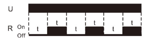
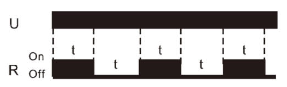
B Repeat Cycle Starting Off |
When input voltage U is applied, time delay t begins. When time delay t is complete, relay contacts R change state for time delay t. This cycle will repeat until input voltage U is removed. Trigger switch is not used in this function. |
|
|
C Interval Power On |
When input voltage U is applied, relay contacts R change state . Immediately and timing cycle begins. When time delay is complete, contacts return to shelf state. When input voltage U is removed, contacts will also return to their state. Trigger switch is not used in this function. |
|
|
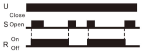
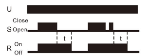
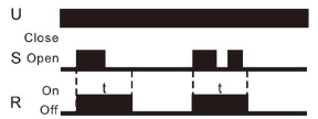
D Off Delay S Break |
Input voltage U must be applied continuously. When trigger S is closed, relay contacts R change state. When trigger S is opened, delay t begins. When delay t is complete, contacts R return to their shelf state. If trigger S is closed before time delay t is complete, then time is reset. When trigger S is opened, the delay begins again, and relay contacts remain in their energized state, if input voltage U is removed, relay contacts R return to their shelf state. |
|
|
E Retriggerable One Shot |
Upon application of input voltage U, the relay is ready to accept trigger signal S. upon application of the trigger signal S, the relay contacts R transfer and the preset time t begins. At the end of the preset time t, the relay contacts R return to their normal condition unless the trigger signal S is opened and closed prior to time out t (before preset time elapses). Continuous cycling of the trigger signal S at a rate faster than the preset time will cause the relay contacts R to remain closed. If input voltage U is removed, relay contacts R return to their shelf state. |
|
|
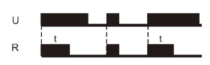
F Repeat Cycle Starting On |
When input voltage U is applied, relay contacts R change state immediately and time delay t begins. When time delay t is complete, contacts return to their shelf state for time delay t. This cycle will repeat until input voltage U is removed. Trigger switch is not used in this function. |
|
|
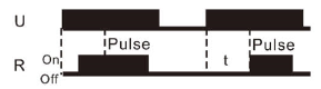
G Pulse Generator |
Upon application of input voltage U ,a single output pulse of 0.5 seconds is delivered to relay offer time delay t. Power must be removed and reapplied to repeat pulse. Trigger switch S is not used in this function. |
|
|
H One Shot |
Upon application of input voltage U, the relay is ready to accept trigger signal S. Upon application of the trigger signal S, the relay contacts R trasher and the preset time t begins. During time-out, the trigger signal S is ignored. The relay resets by applying the trigger signal S when the relay is not energized. |
|
|
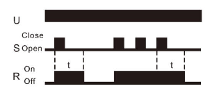
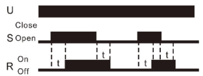
I On/Off Delay S Make/Break |
Input voltage U must be applied continuously. When trigger S is closed, time delay t begins. When time delay t is complete, relay contacts R change state and remain transferred untill trigger S is opened. If input voltage U is removed, relay contacts R return to their shelf state. |
|
|
J Memory Latch S Make |
Input voltage U must be applied continuously. Output changes state with every trigger S closure. If input voltage U is removed, relay contacts R return to their shelf sate. |
 |

|
Output Characteristics |
Timing Characteristics |
||
|
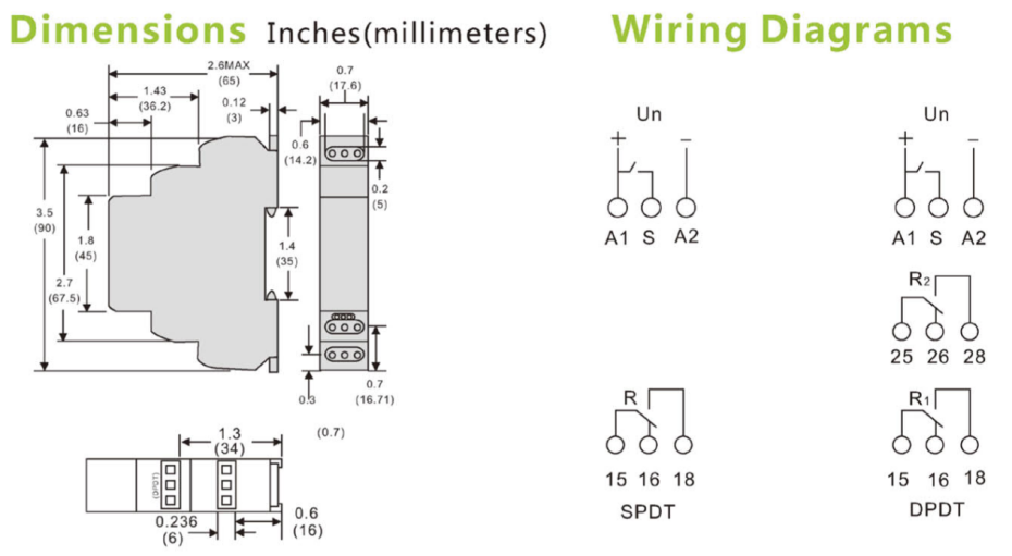
Number and type of contacts |
SPDT or DPPT |
Functions Available |
10 |
|
Contact Material |
Silver Alloy |
Time Scales |
10 |
|
Current Rating |
15@240VAC, 24VDC |
Time Ranges |
0.1 sec to 10 days |
|
Switching Voltage |
240V 50/60Hz |
Tolerance(Mechanical Setting) |
5% |
|
24VDC |
Repeatability(Constant Voltage and Temperature) |
0.2% |
|
|
1/2HP@120V 50/60Hz |
Reset Time(Maximum) |
150ms |
|
|
1HP@240V 50/60Hz |
Trigger Pulse Length(Minimum) |
50ms |
|
|
B300 Pilot Duty |
|||
|
Minimum Switching Requirement |
100mA |
||
|
Indication |
Red LED |
||
|
Input Characteristics |
Performance Characteristics |
|||
|
Voltage Range |
12 to 240V 50/60Hz/VDC |
Electrical Life(Operations@Rated Current) |
100,000 Cycles(Resistive) |
|
|
Operating Range(% of Nominal) |
85% to 110% |
Mechanical Life(Unpowered) |
10,000,000 Cycles |
|
|
Maximum Consumption |
3VA(AC) |
Dielectric Strength |
Input to Contacts |
2500VAC |
|
1.7W(DC) |
Between Open Contacts |
1000VAC |
||
|
Indication |
Green LED |
Terminal Wire Capacity |
14AWG(2.1mm2) |
|
|
Terminal Torque(Maximum) |
7.1 ibf in(0.8Nm) |
|||
| Environment | ||
| Product Certifications | CE, RoHS | |
| Ambient Air TemperatureAround the device | Storage | -30 to +70(-22 to +158F) |
| Operation | -20 to +55(-4 to +131F) | |
| Degree of Protection | IP20 | |
| Weight | 65Grams(2.3 oz) | |
|
Relay Contact 15A |
Load |
||||||||
|
|
|
|
|
|
AC1 |
AC3 |
AC15 |
DC1(24/110/220V) |
|
|
AgNi |
1000W |
4000VA |
0.9kW |
750V |
15A/0.5A/0.35A |
||||


Products categories
-
Secondary bracket single spool, secondary rack ...
-

Disconnector R7 100A single pole 230V 2P 3P 4P...
-

YUANKY HWC100 GPRS 3G 4G NB-IOT smart prepaid e...
-

Cable puller Electrical supply wire puller cabl...
-
Wholesale OEM China Gwiec Creative Products WiF...
-

YUANKY combination socket no gas leak 1-16KGF P...